Aftercoolers
United Heat Transfer Pvt. Ltd, is an OEM supplier of After coolers to many manufacturers in the Industrial Compressor and engineering industries. UHT supplies heat exchanger for cooling air/Gas discharged from compressors. It provides the most effective means of removing moisture from compressed air and gases.
DESIGN AS PER ASME Section VIII Div. 1, Div. 2,TEMA API 660, 661, IS 2825 & IS 4503.
After cooler:
Water or moisture is not desirable in the transmission lines of an air compression system. Water carried through the lines washes away lubricating oil from the tools the compressed air is running. This causes the tools to operate sluggishly & increases the need for maintenance. The effect is compounded in high-speed tools, where wearing surfaces are limited in size & excessive wear reduces efficiency by creating air leakage.
Further problem results from the decrease of temperature caused by sudden expansion of air at the end. This low temperature creates condensation, which freezes around port and valves & impairs efficiency. These conditions can be minimized by removing the moisture from the air directly after compression before the air enters the distribution system.
The compressed air discharged from compressor is hot. Compressed air at these temperatures contains large quantities of water in vapor form. As the compressed air cools this water vapor condenses into a liquid form. As an example, if an after cooler is not used, a 200 SCFM compressor operating at 100 psig introduces 45 gallons of water into the compressed air system each day.
Functions of compressed air After Coolers:
- Cool air discharged from air compressors via the heat exchanger.
- Reduce risk of fire (Hot compressed air pipes can be a source of ignition).
- Reduce compressed air moisture level.
- Increase system capacity.
- Protect downstream equipment from excessive heat.
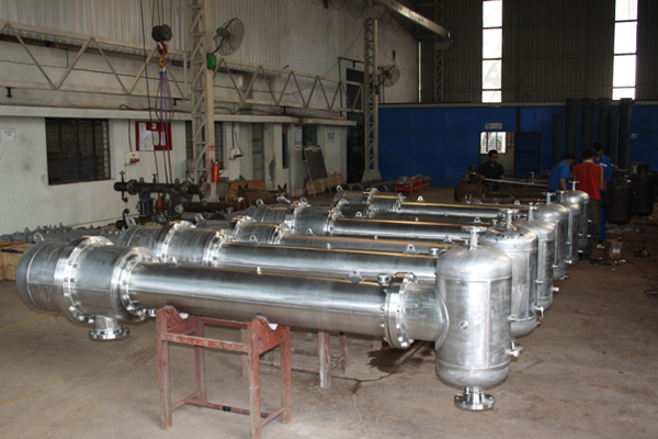
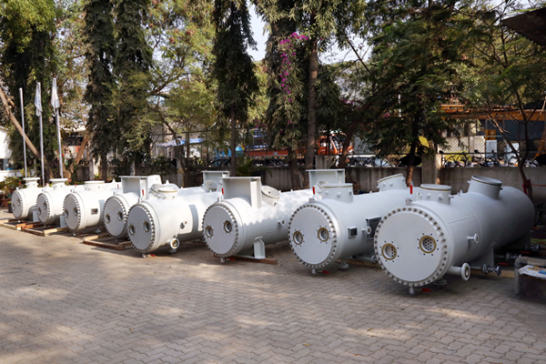
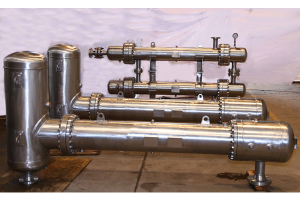
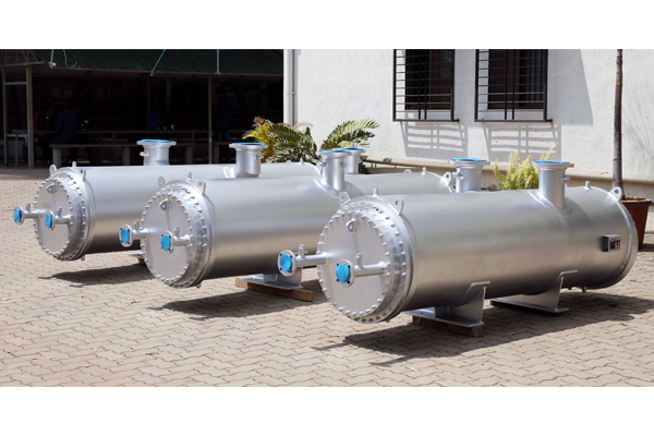
Pipeline After cooler with moisture separator: A water-cooled pipeline after cooler comes in different styles. The most common style for compressed air service is a Shell and Tube Heat Exchanger/After cooler. The pipeline after cooler consists of a shell with a bundle of tubes fitted inside. Typically, the compressed air flows through the tubes in one direction as water flows on the shell side in the opposite direction. Heat from the compressed air is transferred to the water. Water vapor forms as the compressed air cools. The moisture is removed by the moisture separator and drain valve. A modulating valve is recommended to maintain a consistent temperature and reduce water consumption. The tube bundles can be fixed or removable. Fixed tube bundles cost less but are more difficult to maintain than bundles that can be removed for cleaning or service.
A moisture separator installed at the discharge of the after cooler removes most of the liquid moisture from the compressed air. Utilizing centrifugal force, moisture collect at the bottom of the moisture separator. An automatic drain should be used to remove the moisture and solids. Moisture Separator with Demister Pad are the Chevron type which consist of a set of specially designed vanes with a well-defined geometry.
VFH (Vertical Flow – Horizontally Placed)
HFV (Horizontal Flow – Vertically Placed)
Gas with entrained liquid droplets flows between the vanes of the Demister Pad. The gas can easily take the turns while the liquid droplets cannot follow the gas streamlines and impinge upon the walls of the vanes and coalesce to a size where they drop down and are collected and removed.
Efficiency:
Moisture Separator are largely used for the separation of coarse mist (or spray) from gases and vapours. A limit drop size (Dp) is used to characterize them, and it is defined as the smallest particle which can be removed to an extent of 99%.
Pressure Drop:
Due to the large percentage of the cross section available for gas flow, the pressure drop in a vast majority of applications is less than 250-500 mm WC. As mentioned above, for high efficiency applications, a larger pressure drop is to be expected.
Thermal Calculation are done on the based-on suction condition
- Normal condition (0 °C, 760 mmHg)
- Standard Condition (16 °C, 760 mmHg)
- Actual Volume
- As per customer’s requirement
Material of Construction:
Size ranging from 80mm to 2500mm in diameter & 12 meter in length
Shell:
- 90/10 Cupro-nickel
- 70/30 Cupronickel
- Carbon steel
- Stainless Steel – 304, 304L, 316, 316L
- Hastelloy
- Inconel
- Monel
Tube Sheet:
- 90/10 Cupronickel
- 70/30 Cupronickel
- Carbon steel
- Naval Brass
- Stainless Steel – 304, 304L, 316, 316L
- Hastelloy
- Inconel
- Monel
Tubes:
- 90/10 Cupronickel
- 70/30 Cupronickel
- Copper
- Stainless Steel – 304, 304L, 316, 316L
- Al. Brass
- As per customer requirement
Channels / Headers/ End Covers:
- Cupronickel
- Nickel Aluminium Bronze
- Gunmetal-Naval Grade
- Graded Cast iron
- Carbon steel
- Stainless Steel – 304, 304L, 316, 316L
- Hastelloy
- Inconel
- Monel